

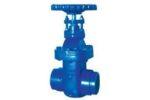
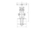
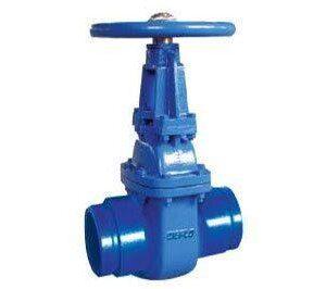
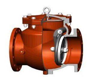
WEFLO Grooved Ends NRS Metal Seated Gate Valve , FIG.3924
Reviews (0)
Shipping & Delivery
Related products
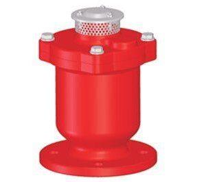
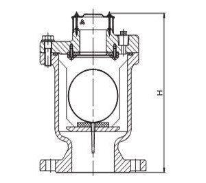
WEFLO Sing Orifice Air Relief Valve FIG.9105
Specifications:
Provides the functions of both Air Release and Air / Vacuum Valves.
Exhausts large quantities of air at system start-up.
Provides protection from pipeline collapse due to vacuum.
Incorporates both features within one valve, More compact and economical.
Flange and drilling to A N S I B16. 1 Class125(Other flange types available upon request) e Rated Working Pressure 300 psi.
UL Listed.
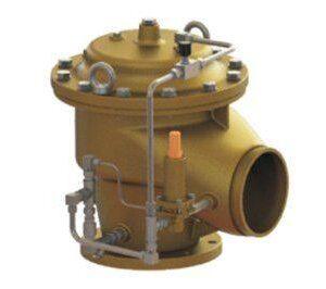
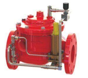
WEFLO Angle Fire Pump Relief Valve FL x Gr Ends FIG.F1339
Specifications :
- Flanged to EN 1092-3 PN16. ANSI Class 150/300. (Other available on request)
- Grooved Ends to AWWA C606 Standard.
- Opens quickly: maintains pressure within close limits.
- Wide range adjustable : 65psi-300psi (4.5 bar-21 bar).
- Limits maximum pump discharge pressure.
- Factory tested & preset to requirements.
- Applicable for water. sea water & foam.
- 300psi (21bar) high Working Pressure 600psi (42bar) Hydrostatic Test
- Pilot operated main valve.
- Reduced cavitation design.
- Simple field adjustable pressure setting, requiring no special tools or system down time.
- Closes gradually for surge-free operation.
- UL 1478 Listed and FM 1361 Approved.
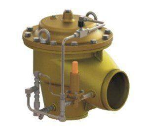
WEFLO Angle Fire Pump Relief Valve Gr x Gr Ends FIG.F1339
Specifications :
- Grooved Ends to AWWA C606 Standard.
- Opens quickly: maintains pressure within close limits.
- Wide range adjustable: 65psi-300psi(4.5 bar-21 bar).
- Pilot operated main valve.
- Reduced cavitation design.
- Limits maximum pump discharge pressure.
- Factory tested & preset to requirements.
- Applicable for water, sea water & foam.
- 300psi(21bar)high Working Pressure 600psi (42bar) Hydrostatic Test
- Simple field adjustable pressure setting, requiring no special tools or system down time.
- Closes gradually for surge-free operation.
- UL 1478 Listed and FM 1361 Approved.
WEFLO Pressure Relief Valve FL x FL Ends-FIG.F1319
Specifications:
Relief Valve: Limits inlet pressure by relieving excess pressure.
Pressure sustaining: Prevents pipe line pressure from rising toa maximum valve.
*Operates over a Wide Flow Range.
*Inlet Pressure Adjustment Range: 65-300psi.
Quick opening and adjustable closing speed.
Flanged to EN 1092-2 PN16,ANSIClass125/150/250.
(Other available on request)Rated Working Pressure 300 psi.
UL 1478 Listed and FM 1361 Approved.
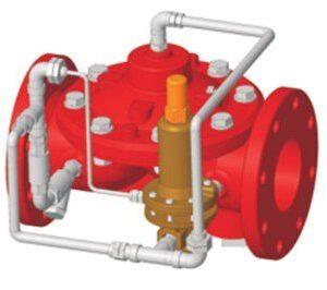
WEFLO Pressure Reducing Valve FIG.F1321-300
Specifications
Multiple End Types for Main Valve:
Flange by Flange, Flange by Groove, Groove by Groove. Pressure Relief Valve:
Limits pipe line pressure by release excess pressure.
Pressure sustaining: Prevents pipe line pressure from rising to a maximum value.
Operates over a wide flow range.*Inlet pressure adjustment range: 65~180psi.Can be maintained without removal from the pipe line.
Flanged to EN1092-2 PN10/PN16,ANSI B16.1 Class125(Other available on request)
Grooved ends to AWWA C606 Standard.
Rated Working Pressure: 300 psi.
Adjustment Range of Set Pressure: 65 to 180 psi.Fusion Bonded Epoxy Coated Interior and Exterior to AWWAC550 Standard.FM 1361 Approved.CNBOP Certified.

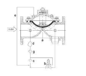
WEFLO Angle Fire Pump Relief Valve FL x FL Ends F1329
Specifications:
Flanged to EN 1092-2 PN16,ANSI Class125/150/250.
(Other available on request)
Opens quickly: maintains pressure within close limits.
Wide range adjustable:65psi-300psi(4.5 bar -21 bar).
Pilot operated main valve.
Reduced cavitation design.
Simple field adjustable pressure setting, requiring no special tools or system down time.
Closes gradually for surge-free operation.
UL 1478 Listed and FM 1361 Approved.
*Limits maximum pump discharge pressure.
*Factory tested & preset to requirements.
Applicable forwater, foam.
300psi(21bar)high Working Pressure
600psi(42bar)Hydrostatic Test
Fusion Bonded Epoxy Coated Interior and Exterior toAWWA C550 Standard.
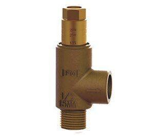
WEFLO Adjustable Relief Valve FIG.F1329
General Description
F1329 bronze adjustable relief valve is rated for up to 310 psi. The adjustable relief valve allows for the required NFPA field hydrostatic testing to be accomplished without removing and/or plugging the outlet for the relief valve. Note: Visual calibration lines on valve are used for approximate adjustment, must verify pressure setting with pressure gauge.
Reviews
There are no reviews yet.